What is TCP/IP – pg2
Origins & History of TCP/IP
- Advanced Research Projects Agency (ARPA), funded an academic research project involving a special type of long-haul (long-distance) network, called a packet-switched network.
- In a packet-switched network environment, individual chunks of data (called packets) can take any usable path between the sender and receiver. The sender and receiver are identified by unique network addresses, but the packets are not required to follow the same path in transit (although they often do). The network built as a result of this project was known as the ARPANET.
TCP/IP’s Design Goals pg 3
- The design of the ARPANET and protocols that evolved to support it were based on the following government needs:
- A desire for a communications network with the ability to withstand a potential nuclear strike
- A desire to permit different kinds of computer systems to communicate easily with one another
- A need to interconnect systems across long distances
TCP/IP Chronology
- 1978 – beginning of IPv4
- 1983 – key points during this time
- 1993 – InterNIC
Who “Owns” TCP/IP pg 4
- both everybody and nobody
Standards Groups That Oversee TCP/IP
- Internet Society (ISOC) – This is the parent organization for all Internet boards and task forces.
- Internet Engineering Task Force (IEFT) – This is the group responsible for drafting, testing, proposing, and maintaining official Internet Standards (in the form of RFCs) through the participation of multiple working groups under its purview.
- Internet Research Task Force (IRTF) – This group handles the more forward-looking activities of the ISOC, including research and development work for topics too far out or impractical for immediate implementation but may play a role on the Internet someday.
- Internet Corporation for Assigned Names and Numbers (ICANN) – This group has the ultimate responsibility for managing Internet domain names, network addresses, and protocol parameters and behaviors.
IPv4 and IPv6
- IPv4 uses 32-bit addresses, which means it supports around four billion distinct network addresses, of which over three billion are usable on the public Internet.
- IPv6 supports 128-bit addresses, which means that its address space is roughly 3.4 * 1038, whereas IPv4’s is roughly 4.3 * 109; that means the IPv6 address space is roughly 8 * 1028 larger than the IPv4 space.
TCP/IP Standards and RFCs pg 7
- A potential Standard RFC begins its life when a process or protocol is developed, defined, and reviewed, and it is then tested and reviewed further by the Internet community. After it is revised, tested further, proven to work, and shown to be compatible with other Internet Standards, it may be adopted as an official Standard RFC by the IETF. It is then published as a Standard RFC and assigned a number.
- Best Current Practice (BCP) does not define a protocol or technical specifications; rather, it defines a philosophy, or a particular approach, to a network design or implementation that is recommended as tried and true, or that enjoys certain desirable characteristics worthy of consideration when building or maintaining a TCP/IP network.
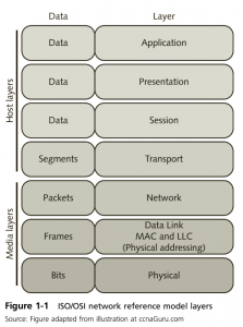
OSI Network Reference Model
- Governed by ISO Standard 7498, the ISO/OSI network reference model, also known as the reference model or the seven-layer model, was developed as part of an international standards initiative in the 1980s that was intended to usher in a new and improved suite of protocols to replace TCP/IP. Although the OSI protocols were never widely adopted outside Europe, the network reference model provides a standard way to talk about networking and explain how networks operate. Despite the 10-year, multibillion-dollar effort to complete the OSI protocols and services, TCP/IP remained the open standard protocol suite of choice and remains so to this day.
- Figure 1.1 – pg 9 (know the layers)
- PDUs typically include “envelope information” in the form of specific headers and trailers. In this context, a header represents a layer-specific label for whatever PDU it precedes. Likewise, a trailer (which may be optional for some layers and some specific protocols) may include error-detection and error-correction information, explicit “end of data” flags, or other data designed to clearly indicate the end of a PDU.
- Know and understand what is being done at what layers (review from last term)
TCP/IP Network Model
- Because TCP/IP’s architecture was designed long before the OSI reference model was finalized in the 1980s, it should come as no surprise that the design model that describes TCP/IP differs somewhat from the OSI reference model. Figure 1-2 shows the layers identified for the native TCP/IP model and maps its layers to those of the reference model. These layers are quite similar, but not identical, to the layers in the OSI reference model. That’s because some functions associated with the Session layer and the Presentation layer in the OSI reference model appear in the TCP/IP Application layer, whereas some aspects of the Session layer in the OSI reference model appear in the TCP/IP Transport layer.
- By and large, the Transport layers for both models map together quite well, as does the Network layer from the OSI reference model and the Internet layer from the TCP/IP model. Just as the TCP/IP Application layer more or less maps to the Application, Presentation, and Session layers in the OSI reference model, the TCP/IP Network Access layer maps to the Data Link and the Physical layers in the OSI reference model.
TCP/IP Network Access Layer pg 16
- 802.X
- 802.1 Internetworking – A general description of how internetworking (exchanging data from one physical network to another) works for the entire 802 family.
- 802.2 Logical Link Control – A general description of how logical links between two devices on the same physical network may be established and managed.
- 802.2 Media Access Control (MAC) – A general description of how media interfaces are identified and accessed on a network, including a scheme to create unique MAC layer addresses for all media interfaces.
- 802.3 CSMA/CD – A general description of how the networking technology more commonly called Ethernet operates and behaves. Ethernet is a shared medium that supports multiple access; it uses a special signal called carrier sense to detect when the medium is in use, and likewise uses special circuitry to detect when two transmissions run into each other (collision detection). In fact, CSMA/CD stands for Carrier Sense Multiple Access with Collision Detection. The Ethernet family includes Gigabit Ethernet (802.3z), as well as 10-Mbps, 100-Mbps, 1000-Mbps, and 10-Gbps varieties, despite the name for 802.12 being “High-Speed Networking.” The latest 802.3 standards that cover 100G/40G Ethernet are 802.3bm, for optical fiber, and 802.3-2015, otherwise known as 802.3bx. The latter is a consolidated revision of the 802.3 standard, which includes amendments 802.2bk/bj/bm. Proposed standards for 2016 include 802.3bq, which is 40GBASE-T for four-pair balanced twisted-pair cabling with two connectors over 30-meter distances, and 802.3by, which is 25G Ethernet.
- 802.5 Token Ring – A general description of how the networking technology developed at IBM, known as token ring, operates and behaves. Note that Fast Ethernet and Gigabit Ethernet have largely replaced token ring, and 802.5 standards development has come to a standstill.
- 802.11 Wi-Fi – A family of wireless packet radio networking standards that supports networking speeds from 1 Mbps to as high as 1,300 Mbps (theoretical maximum). The most common members of this family are the 11 Mbps 802.11a and 802.11b standards, the 54 Mbps 802.11g standard, the 72 to 150 Mbps 802.11n multichannel technology, and 802.11ac, with bandwidth rated up to 450 Mbps on the 2.4 GHz band and 1,300 Mbps on the 5 GHz band.
- Network access layout protocols
- PPP – used to establish a direct connection between a pair of networked devices, and can provide connection authentication to establish the identities of both parties, apply encryption to transmissions to ensure privacy, and apply compression to reduce transmission data volume
- High-Level Data Link Control (HDLC) protocol—Based on IBM’s Synchronous Data Link Control (SDLC) protocol, HDLC uses data frames to manage network links and data transmission.
- Frame relay—A telecommunications service designed to support intermittent data transmission between LANs and wide area network end points. Frame relay uses data frames to manage network links and data transmission. However, frame relay is slowly being phased out by most major ISPs but is still used for connections in rural areas that do not have access to Digital Subscriber Line and cable modem services. Sprint no longer offers frame relay, Verizon discontinued it in 2015, and although AT&T also discontinued it, the company will support existing customers until 2016.
- Asynchronous Transfer Mode (ATM)—A high-speed, cell-oriented connection-switching technology used for digital voice and data communications. ATM is widely used for telecommunications and data networking backbones and infrastructure.
- PPTP – Point-to-Point Tunneling Protocol
- VPN – Virtual Private Network
- The TCP/IP Internet layer protocols handle routing between machines across multiple networks and also manage network names and addresses to facilitate the routing.
- MTU fragmentation – When a router carries data from one type of network to another, the largest chunk of data that the network can carry, an MTU, varies. When data moves from a medium that supports a larger MTU to a medium that supports a smaller MTU, that data must be reduced to smaller pieces to match the smaller of the two MTUs. This only needs to be a one-way transformation, given that smaller packets don’t have to be combined into bigger ones in the opposite direction, but it must be performed while the data is in transit.
- Addressing – This is the mechanism whereby all network interfaces on a TCP/IP network are associated with unique bit patterns that identify each interface individually and also identify the network (or even the network locale) to which that interface belongs.
- Routing – Routing—This is the mechanism that forwards packets from sender to receiver, in which numerous intermediate relays may be involved in achieving delivery from sender to receiver. This function includes not only the processes involved in successful delivery but also the methods to track delivery performance and report on errors when delivery fails or is otherwise hampered.
- Internet Layer Protocols
- IP
- ICMP
- ARP
- RARP
- BOOTP
- RIP
- OSPF
- BGP
TCP/IP Transport Layer
- TCP is connection-oriented and UDP is connectionless.
- Protocols [TCP, UDP]
TCP/IP Application Layer
- this is where the protocol stack interfaces with applications or processes on a host machine. The user interfaces to a process or application are defined here. The common overlap between TCP/IP protocols and services occurs here as well.
- Daemons – In UNIX terminology, a special “listener process,” called a daemon, operates on a server to handle incoming user requests for specific services.
- When a connection request arrives, the listener process checks to see if the request should be allowed to proceed. If so, it creates another temporary process (on UNIX) or spawns a separate execution thread (on Windows Server 2012) to handle that particular request. This temporary process or thread lasts only long enough to service that user request and uses temporary port addresses in the range from 1025 through 65535 to handle it.
TCP/IP Protocols, Services Sockets, and Ports pg 21
- – general info on how all of this works (as described in the book / lectures)
- – Know the role of Protocol numbers – NOTE You do NOT need to know specific #’s from Table 1.1 on pg 22
- – Port Numbers
- – Sockets
Protocol Analysis pg24
- Protocol analysis is the process of tapping into the network communications system, capturing packets that cross te network, gathering network statistics, and decoding the packets into readable form.
- Promiscuous Mode Card and Driver – Packets enter the system from the network interface card. A card that runs in promiscuous mode can capture broadcast packets, anycast packets, multicast packets, and unicast packets sent to other devices. It can also see error packets such as ethernet collision fragments, oversized packets, undersized packets (runts), and packets that end on an illegal boundary.
- Packet Filters – Defines the type of packets the analyzer wants to answer
- Trace Buffers – Holding area for packets copied from the network.
- Decodes are applied to the packets that are captured in the trace buffer
- Alarms – configurable alarms that indicate unusual network events or errors.
- Excessive broadcasts
- Utilization threshold exceeded
- Request denied
- Server down
- Statistics – network performance stats such as current packet-per-second rate or network utilization rates.
Placing a Protocol Analyzer
- A protocol analyzer can only capture packets that it can see on the network. In some cases, you can place the analyzer on a network close to the device of interest. In other cases, you must reconfigure network devices to ensure the analyzer can capture packets.
- By placing a hub between a device of interest and the switch, and by connecting the analyzer to the hub, you can view all traffic to and from the device.